Raspberry Pi Case DIY
I finally got myself a Raspberry Pi and it obviously needs a case. (By the way, it runs the ARM version of Arch Linux, naturally.) Of course I wanted to build one myself, rather than buying one of those boring cases that almost cost more than the device itself. I already had a vague idea about the concept but nothing solid yet. The concept had to be simple (but solid), because besides a Dremel and an electric drill I only had standard tools at hand. (You do not even need a Dremel if you have a small saw instead.)
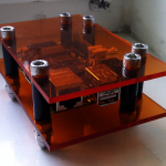
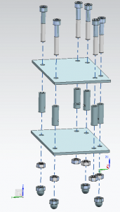
My idea was to build a “sandwich“, with two translucent plates made of acrylic polymer and the Raspberry Pi between it. The plates should be hold in place by threaded rods or screws secured with nuts. That is one of my favorite construction designs, since I made myself a TNT FleXy Table. This design may look like it is fragile, but it is incredibly solid. I had not yet decided how to hold the Raspberry Pi itself in place.
When I browsed the cases page over at the Raspberry Pi Wiki to see what other people came up with, there was also one particular case which already came very close to the concept I had in mind. It looks quite nice, but in my opinion it has a few flaws. I did not like to force the screws into (unthreaded) polymer spacers, as dismanteling the case a few times would damage it. Due to the countersunk screws, the acrylic glas plates lie flat on the sub floor, which will give it lots of scratches. (Yes, maybe I think too much.^^) I kept it’s original dimensions, which were already optimum.
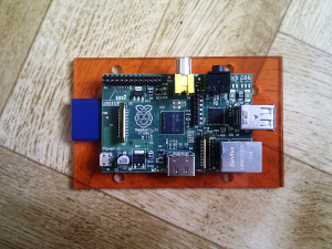
Anyway, what I liked about that case was the solution for holding the Raspberry Pi in place by making a small notch on each spacer – it is ideal.
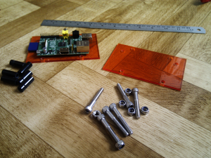
Here is what you need (dimensions in [mm]):
- two plates (120x75x3)
- six screws (M6x40; hexagon socket, flat headed)
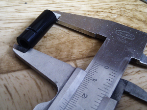
- six spacers (inner diameter 6, outer diameter approximately 9, length 25; small notch at 6)
- six nuts (M6)
- four dome nuts (M6)
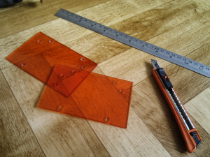
It does not really matter what kind of plates are used, as long as you can cut it and drill holes in it. I simply bought one orange acrylic glas plate in a nearby material shop. They have it in all kinds of colors for 1 EUR. You could probably also use three sheets of CD case covers instead (although cutting will be more difficult). The nice thing about acrylic polymers is that they are rather brittle, which makes it possible to cut it creating very slick edges. Use a simple cutter or other sharp knife and a ruler to create a predetermined breaking line and break it (e. g. over the edge of a table). Breaking it slowly is crucial. Doing it too abruptly (for example with a hammer) will result in unclean edges. Please do not buy a dedicated acrylic glas cutter for that. The employee was trying to sell one to me, that cost about 15 EUR! That is completely unnecessary, any sharp object will to the job just fine.
Most M6x40 screws with flat heads can be used. I chose six DIN EN ISO 4762 M6x40 screws (8.8 high strength of course^^).
There is not much to do wrong with the six nuts and the four dome nuts, as long as they are M6. Just buy the standard ISO 4032 M6 and DIN 1587 M6 nuts or use six self-locking nuts instead (ISO 10511).
The parts most difficult to buy are probably the spacers. I just could not find anything like it. Even the polymer tube, from which I cut the spacers was hard to come by. And with about 4 EUR it was incredibly expensive for a piece of trash. It still gives me nightmares sometimes. (Please let me know if there is any cheaper way to get one!)
After you cut the plates, make the spacers. I used a Dremel (alternatively a saw) to cut them from the polymer tube I bought, and then sanded the ends plane. Make the small notch at 6 mm on each spacer using your Dremel or saw. Do not cut too deep or make it too big, it only has to catch the edges of the circuit board.
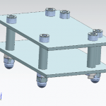
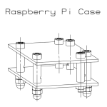
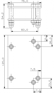
The most difficult step is drilling the holes. You can get the locations of them from the CAD draft I supplied at the end of this post. But really, do not try to implement it too accurate. It is just the ideal CAD concept design drawing. Drilling by hand will inevitable result in (bigger or smaller) tolerances. The best way to do this is by taping both plates temporarily together (so that the holes you drill will be identical), putting the Raspberry Pi centered on top (mind the overlap of the SD card!) and mark the drilling points. But be cautious to choose points at which the spacers will not be in the way of any plugs or small diodes, of course! Use my design drawings as reference, if you want. I also used a slightly bigger drill head (> 6 mm), because of the tolerances. This has another good side effect: Besides the fact that you will increase chances that your Raspberry Pi will actually fit into the casing, the tolerances will help reducing the mechanical stress on the circuit board. Do not worry, doing that will not reduce stability, it will still be very solid.
Assembly should be self-explanatory. If you came this far and feel lost now, you probably never played LEGO. Ask your five year old son or daughter to help you out or join them inconspicuously playing LEGO for a week.
About the CAD drafts: They are just quick and dirty drawings and not DIN-/ or ISO-compliant whatsoever. Do not expect anything fancy. However, they should provide all necessary details for construction and assembly. All measurements are in [mm]/metric system.
CAD drafts:
