<?xml version="1.0" encoding="utf-8"?><feed xmlns="http://www.w3.org/2005/Atom" ><generator uri="https://jekyllrb.com/" version="3.10.0">Jekyll</generator><link href="/feed.xml" rel="self" type="application/atom+xml" /><link href="/" rel="alternate" type="text/html" /><updated>2026-06-26T13:31:20+00:00</updated><id>/feed.xml</id><title type="html">fomori blog</title><subtitle>The fomori blog is a collection of hacks and thoughts of devsnd and 6arms1leg.</subtitle><entry><title type="html">Fixing display freezing with AMD GPU on kernel 7.0.0</title><link href="/blog/linux/fix/2026/06/26/Fix-AMD-GPU-display-freeze.html" rel="alternate" type="text/html" title="Fixing display freezing with AMD GPU on kernel 7.0.0" /><published>2026-06-26T00:00:00+00:00</published><updated>2026-06-26T00:00:00+00:00</updated><id>/blog/linux/fix/2026/06/26/Fix-AMD-GPU-display-freeze</id><content type="html" xml:base="/blog/linux/fix/2026/06/26/Fix-AMD-GPU-display-freeze.html"><![CDATA[<p>Hey, it’s been a while. Took me a good ten years since the last blog post, so this one better be worth it! Here’s my problem. Everytime I boot up my framework laptop (Framework Laptop 13 AMD, Ryzen 7 7840U / Radeon 780M), my laptop screen freezes and only my external screen keeps working. There is a manual workaround for this problem, just deactivate the laptop-screen and reactivate it in the display settings, but I want a permanent fix/workaround.</p>

<hr />
<h3 id="intermission-queue-muzak-organ-music">Intermission (queue muzak organ music)</h3>
<p>Kept you waitin’, huh? So why would I start again to blog after 10 years of silence? I decided that with all the clankers around, I’d rather add some organic home-grown hand-made text to the primordial soup of the T1000 while I still have the time. But in all seriousness: I don’t want this web to die, so I’ll try to fight the second <a href="https://en.wikipedia.org/wiki/Eternal_September">eternal september</a>. This time it’s not humans flooding the net, but bot and my way to go about it is not to go out with a wimper! So I start publishing my little hacking adventures again.</p>

<hr />

<p>Checking <code class="language-plaintext highlighter-rouge">dmesg</code> I get this:</p>

<div class="language-plaintext highlighter-rouge"><div class="highlight"><pre class="highlight"><code>[   35.439555] amdgpu 0000:c1:00.0: [drm] REG_WAIT timeout 1us * 100 tries - dcn31_program_compbuf_size line:141
[   35.439872] ------------[ cut here ]------------
[   35.439875] WARNING: amd/amdgpu/../display/dc/hubbub/dcn31/dcn31_hubbub.c:151 at dcn31_program_compbuf_size+0xcc/0x230 [amdgpu], CPU#0: kworker/0:2/180
</code></pre></div></div>

<p>And I found a <a href="https://github.com/CachyOS/linux-cachyos/issues/810">bug report on github that reports the same error</a> and this <a href="https://gitlab.freedesktop.org/drm/amd/-/work_items/4403">kernel ticket</a>, and I actually got nerd sniped by the problem, and started to tinker with patching my kernel to try and fix the issue, but then I remembered. I don’t have time for this and neither do you.</p>

<p>So just:</p>
<div class="language-plaintext highlighter-rouge"><div class="highlight"><pre class="highlight"><code>sudo nano /etc/default/grub
</code></pre></div></div>
<p>add “amdgpu.dcdebugmask=0x410” to kernel boot parameters, like so:</p>
<div class="language-plaintext highlighter-rouge"><div class="highlight"><pre class="highlight"><code>GRUB_CMDLINE_LINUX="amdgpu.dcdebugmask=0x410"
</code></pre></div></div>
<p>and regenerate grub config</p>
<div class="language-plaintext highlighter-rouge"><div class="highlight"><pre class="highlight"><code>sudo update-grub
</code></pre></div></div>

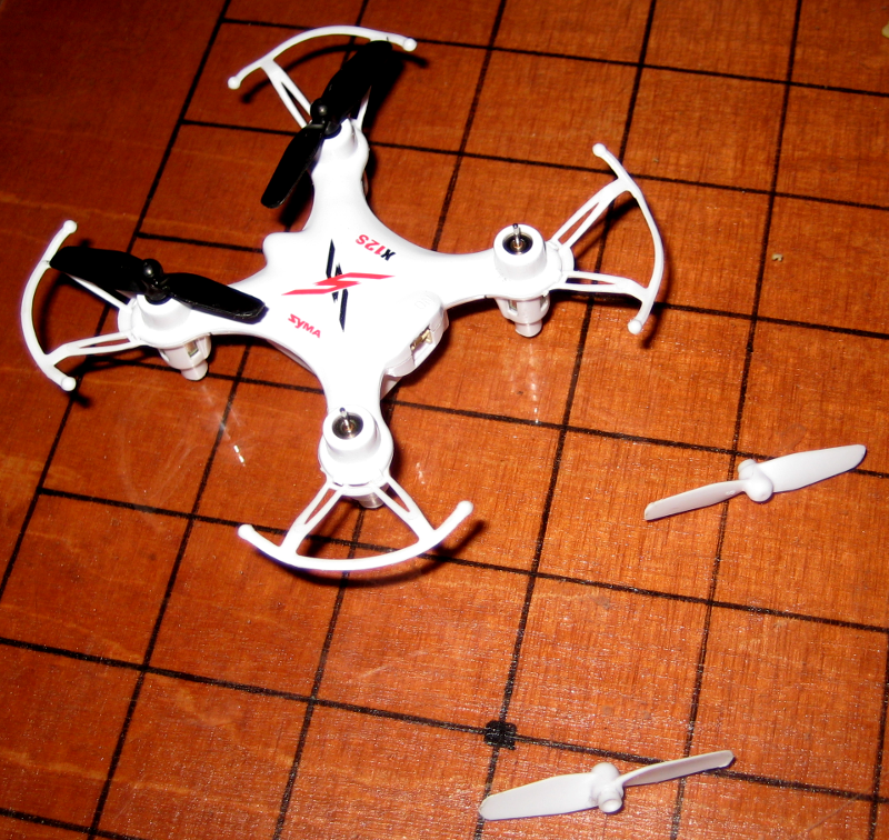
<p>That’s it. You’ve thrown out a bit of battery life for a working screen, an excellent trade-off for the time being. I hope I saved you some time.</p>]]></content><author><name>devsnd</name></author><category term="blog" /><category term="Linux" /><category term="Fix" /><summary type="html"><![CDATA[Hey, it’s been a while. Took me a good ten years since the last blog post, so this one better be worth it! Here’s my problem. Everytime I boot up my framework laptop (Framework Laptop 13 AMD, Ryzen 7 7840U / Radeon 780M), my laptop screen freezes and only my external screen keeps working. There is a manual workaround for this problem, just deactivate the laptop-screen and reactivate it in the display settings, but I want a permanent fix/workaround.]]></summary></entry><entry><title type="html">Repair the Syma X12S quadcopter by replacing the motors and rotor blades (and what to do if it does not lift off afterwards)</title><link href="/blog/handycrafts/hardware/2015/10/19/Repair_the_Syma_X12S_quadcopter_by_replacing_the_motors_and_rotor_blades__and_what_to_do_if_it_does_not_lift_off_afterwards_.html" rel="alternate" type="text/html" title="Repair the Syma X12S quadcopter by replacing the motors and rotor blades (and what to do if it does not lift off afterwards)" /><published>2015-10-19T21:21:36+00:00</published><updated>2015-10-19T21:21:36+00:00</updated><id>/blog/handycrafts/hardware/2015/10/19/Repair_the_Syma_X12S_quadcopter_by_replacing_the_motors_and_rotor_blades__and_what_to_do_if_it_does_not_lift_off_afterwards_</id><content type="html" xml:base="/blog/handycrafts/hardware/2015/10/19/Repair_the_Syma_X12S_quadcopter_by_replacing_the_motors_and_rotor_blades__and_what_to_do_if_it_does_not_lift_off_afterwards_.html"><![CDATA[<p><a href="/assets/images/Cover.png"><img src="/assets/images/Cover-300x213.png" alt="Syma X12S quadcopter with new motors" /></a>My friend owns a Syma X12S <a href="https://en.wikipedia.org/wiki/Quadcopter" title="en.wikipedia.org - quadcopter">quadcopter</a> that was cheaply imported from China. It really is an amazing piece of hardware and the perfect entertainment when you spend an evening with friends. Piloting this miniature aircraft is quite easy – it only takes a few flying sessions until you acquired enough skills to handle it. However, I still managed to crash the quadcopter in a way that damaged two of its four motors. The beauty of this toy is its modular design: Even though it is a cheap product, most of the parts are <a href="https://en.wikipedia.org/wiki/Line-replaceable_unit" title="en.wikipedia.org - Line-replaceable unit">LRU</a>s, so you can simply order a replacement for the defect part and replace it yourself.</p>

<p>This short post shows how to replace the motors of a Syma X12S quadcopter and highlights some difficulties to look out for.</p>

<h1 id="replacing-the-motors">Replacing the motors</h1>

<p>The Syma X12S quadcopter has two pairs of motors, two spinning in one direction and two spinning in the opposite direction. Both motor pairs are placed diagonally in the quadcopter mount positions (see items 04 and 05 in the exploded assembly drawing below). This design concept accounts for the spin moment of each rotor, assuring an equilibrium on the overall spin moment.</p>

<p><a href="/assets/images/Exploded-assembly-drawing.png"><img src="/assets/images/Exploded-assembly-drawing-237x300.png" alt="Exploded assembly drawing - modular design" /></a>Replacing any part of this quadcopter model is straight forward, even for people that are not so technically gifted: The only tools needed are a small <a href="https://en.wikipedia.org/wiki/List_of_screw_drives" title="en.wikipedia.org - List of screw drives">Phillips screw drive</a> and basic soldering equipment. To get access to the motors you only need to remove three parts. First, the rotor blades of the motors need to be removed:</p>

<p><a href="/assets/images/Rotor-blades-removed.png"><img src="/assets/images/Rotor-blades-removed-300x283.png" alt="Rotor blades removed" /></a>They are simply pushed onto the motor shaft, creating a frictional connection. So just reverse the process by pulling them off again. Do not pull on the blades, as they bend and break easily. Instead grab the rotors at the hub.</p>

<p>Next, the bottom cover plate needs to be removed, which is held in place by four screws:</p>

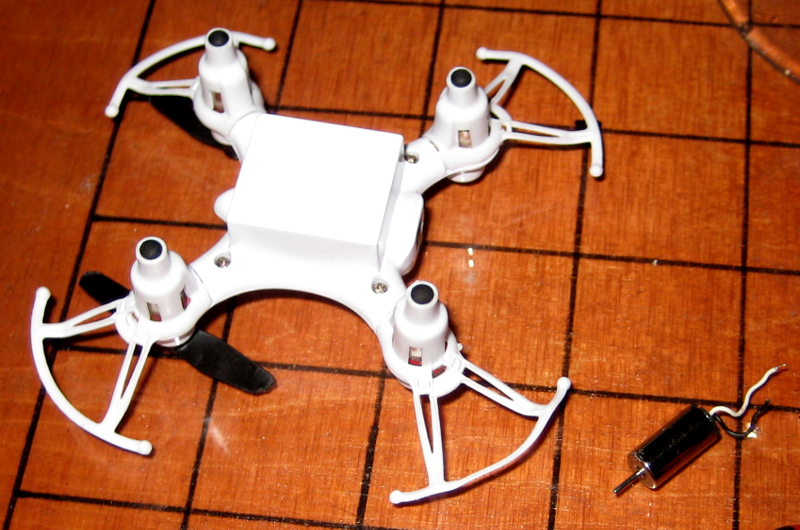
<p><a href="/assets/images/Buttom-cover-plate.png"><img src="/assets/images/Buttom-cover-plate-300x198.png" alt="Buttom cover plate" /></a>Then, remove the chassis parts that cover each motor, which serve as a rotor blade protection and landing gear. Only remove the one(s) on the motor(s) you want to replace. This is probably the most delicate step: Theses parts are kept in place by two tiny clips each. Removing the part without breaking the clips requires a little patience and a steady hand – I ripped one off right away. If you break one of the clips, the part will not be held in place anymore after reassembly (later in this guide). Applying adhesive or a tiny drop of <a href="https://en.wikipedia.org/wiki/Hot-melt_adhesive" title="en.wikipedia.org - Hot-melt adhesive">hot glue</a> will fix this.</p>

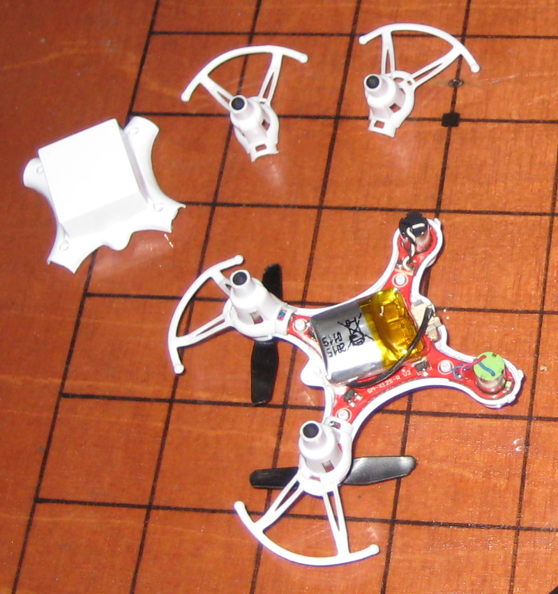
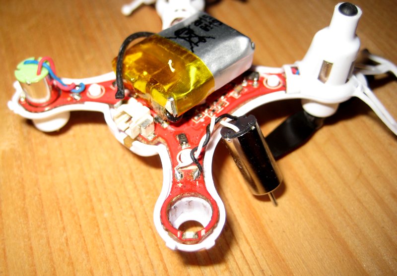
<p><a href="/assets/images/Quadcopter-opened.png"><img src="/assets/images/Quadcopter-opened-282x300.png" alt="Quadcopter opened and ready for motor repair" /></a>The Picture above shows the motors ready for removal. They are simply pushed into the chassis (no adhesive is applied) and the two wires are soldered to the <a href="https://en.wikipedia.org/wiki/Printed_circuit_board" title="en.wikipedia.org - Printed circuit board">PCB</a>. When replacing the motors, make sure to swap it with the correct motor type (The “normal” or counter-spinning motors can easily be distinguished by their wire coloring).</p>

<p><a href="/assets/images/Motor.png"><img src="/assets/images/Motor-300x208.png" alt="Motor close-up" /></a>Finally, reverse the steps above to reassemble the quadcopter again.</p>

<h1 id="difficulties-to-look-out-for">Difficulties to look out for</h1>

<h3 id="never-rotate-the-rotors-manually">Never rotate the rotors manually</h3>

<p>Rotating the motors manually (with your hand or by blowing on the blades) should be avoided. Manually rotating electrical motors <a href="https://en.wikipedia.org/wiki/Electromagnetic_induction" title="en.wikipedia.org - Electromagnetic induction">induces voltage</a> in the circuity. Although most (good) circuits have protection against this phenomenon, it is good practice not to do so.</p>

<h3 id="motor-cable-length">Motor cable length</h3>

<p>The length of the cables is just enough to push the motors into the mounting positions in the chassis <em>after</em> soldering the wires. However, twisting them is not possible then, which makes the bottom cover plate not fit that easily anymore. So ideally, install the motors first and solder the wires last.</p>

<h3 id="rotor-blade-form">Rotor blade form</h3>

<p>Your quadcopter does not lift off after repairing?</p>

<p>Since there are two different motor types spinning in different directions, it is clear that they need different rotor blade forms to create lift (see the exploded assembly drawing shown earlier in this post). The shipped rotor blades came in two different colors (black and white) so I thought that each color marked one of the two rotor forms – why else would there be two black and two white rotors? Well, this was not the case. The rotor color has nothing to do with its form! That was quite confusing to me. So make sure to fit the right rotor blades on each motor.</p>]]></content><author><name>6arms1leg</name></author><category term="blog" /><category term="Handycrafts" /><category term="Hardware" /><summary type="html"><![CDATA[My friend owns a Syma X12S quadcopter that was cheaply imported from China. It really is an amazing piece of hardware and the perfect entertainment when you spend an evening with friends. Piloting this miniature aircraft is quite easy – it only takes a few flying sessions until you acquired enough skills to handle it. However, I still managed to crash the quadcopter in a way that damaged two of its four motors. The beauty of this toy is its modular design: Even though it is a cheap product, most of the parts are LRUs, so you can simply order a replacement for the defect part and replace it yourself.]]></summary></entry><entry><title type="html">Low-Latency Live Streaming your Desktop using ffmpeg</title><link href="/blog/linux/software/2015/08/02/Low_Latency_Live_Streaming_your_Desktop_using_ffmpeg.html" rel="alternate" type="text/html" title="Low-Latency Live Streaming your Desktop using ffmpeg" /><published>2015-08-02T13:43:34+00:00</published><updated>2015-08-02T13:43:34+00:00</updated><id>/blog/linux/software/2015/08/02/Low_Latency_Live_Streaming_your_Desktop_using_ffmpeg</id><content type="html" xml:base="/blog/linux/software/2015/08/02/Low_Latency_Live_Streaming_your_Desktop_using_ffmpeg.html"><![CDATA[<p>I recently bought myself a projector, which I installed in one corner of the room. Unfortunately I didn’t buy a long enough HDMI cable with it, so I could not connect it to my desktop computer and instead used my loyal ThinkPad T60 for playback. But I also wanted to be able to play some games using the projector, for which my laptop wasn’t beefy enough. So I thought, why not just stream the games from my desktop computer to the laptop?</p>

<p>In this post I will explore how to stream 720p (or any quality for that matter) from one computer to another using ffmpeg and netcat, with a latency below 100ms, which is good enough for many games. <strong>TL;DR; If you don’t care about the technical details, just <a href="/blog/?p=1213#thesolution">jump to the end of the post</a> to try it out yourself.</strong></p>

<h1 id="the-problem">The problem:</h1>

<p>Streaming low-latency live content is quite hard, because most video codecs are designed to achieve the best compression and not best latency. This makes sense, because most movies are encoded once and decoded often, so it is a good trade-off to use more time for the encoding than the decoding.</p>

<p>One way to save space or bandwidth is to compress different parts of a movie with varying quality. For example, the h264 encoder will compress fast moving scenes more than a slow scene, because the human eye will not be able to see all the detail in the fast moving scene anyway, while the viewer might inspect the image of a slow scene more thoroughly. But to do so, the encoder has first to find out if it is currently encoding a fast- or slow-moving scene.</p>

<p>There are essentially two ways to find out if the content is fast- or slow-moving: The most commonly used method for non-live content is a so called two-pass encoding, in which the encoder first analyses the whole movie and then, in a second pass, encodes the movie using the information acquired before. Unfortunately this is not possible for live content. The second way to do this is to look ahead for a few frames in the movie material and then to decide adaptively whether this is a slow or a fast scene. Since it is not possible to look ahead in live material, the encoder has to buffer some frames before encoding them, so it can know what’s coming up next. This buffer however introduces latency in the ballpark of seconds rather than milliseconds, which makes it impossible to create an interactive live-stream using this technique. This also is a simplified example, since modern encoders can use multiple reference frames if the past and future of the current frame to reduce the redundancy of image data. These frames are called <a href="https://en.wikipedia.org/wiki/Inter_frame#Typical_Group_Of_Pictures_.28GOP.29_structure">GOP (group of pictures)</a> and those will play a significant role to get to a sub-second latency stream.</p>

<p>Because a low-latency live stream cannot afford the time to analyse the video material up front, live streamed content will always look worse than any other encoded content, and this can only be countered by using more bandwidth.</p>

<p>I found some <a href="http://smorgasbork.com/2009/12/03/real-time-mpeg-2-encoding-with-ffmpeg/">blog posts that explain live-streaming</a> in depth and most of them used the mpeg2video encoder, but most of them “only” wanted real-time encoding, but not necessarily low-latency. I achieved quite good results using mpeg2video, with the lowest latency of all the codecs I tried out, but also wanted to explore if I could achieve better image quality. So I tried out the x264 encoder using the “zerolatency” tuning. While the “zerolatency” tuning did help, I still had a huge latency, far from playing any game on a live stream. So I did a little digging and found a <a href="https://web.archive.org/web/20150421033553/http://x264dev.multimedia.cx/archives/249">thread on the x264dev forums, which I resurrected from the internet archive</a>, in which a lot of additional x264 flags are discussed. The most important one to bring down the latency was to use the smallest possible vbv-bufsize (which is the encoder buffer). Another good advice is to use so called intra-refresh, which means that there aren’t any full key frames anymore, but instead contents of a key frame are transmitted in blocks over time. This means that there is not a burst of data to send for each key frame, but instead parts of the image are refreshed over time. To figure out if some option would improve the latency or not I needed a way to measure it.</p>

<p>I wrote a quick script in python that would output the current time in milliseconds to measure the latency:</p>

<div class="language-plaintext highlighter-rouge"><div class="highlight"><pre class="highlight"><code>#!/usr/bin/python3
import time
import sys
while True:
    time.sleep(0.001)
    print('%s\r' % (int(time.time() * 1000) % 10000), end='')
    sys.stdout.flush()
</code></pre></div></div>

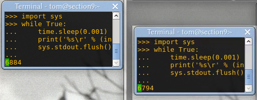
<p>Using this script, I would then encode and decode the stream on my desktop at the same time. Making a screenshot of both the original desktop and the streamed desktop next to it gives me the total system latency.</p>

<p><a href="/assets/images/Screenshot_2015-08-02_14-31-16.png"><img src="/assets/images/Screenshot_2015-08-02_14-31-16.png" alt="Screenshot_2015-08-02_14-31-16" /></a>On the the real desktop the time is at 6884, and on the right the streamed desktop it is at 6794. In this example the stream has a latency of about 90ms</p>

<p>In this way I could measure if any changes I made really improved the latency of my video stream without the network overhead. This would not always be totally accurate, as ffmpeg might take a snapshot of the desktop just before a new image is rendered by the Xwindow system, but should not be too far off.
Using this measurement tool, I made a lot of changes to the encoder options, but at some point I hit a brick wall. I couldn’t get the latency down any further: The client side was buffering the stream as well! I used mplayer to playback my video stream and tried out all kinds of flags like <code class="language-plaintext highlighter-rouge">-nocache</code> and <code class="language-plaintext highlighter-rouge">-framedrop</code>. While all of them helped a bit, mplayer performed best when using the <code class="language-plaintext highlighter-rouge">-benchmark</code> flag… Which seems to bypass anything that is not part of the actual video decoding process, which is exactly what was needed.
After figuring out good settings for the encoder and decoder, I also tried out other transport streams like <a href="https://en.wikipedia.org/wiki/Real-time_Transport_Protocol">RTP</a>, but <a href="https://en.wikipedia.org/wiki/MPEG_transport_stream">mpegts</a> was the faster in my tests. I guess it would be possible to achieve even better latency using ffmpegs UDP stream instead sending the stream over TCP using netcat, but the UDP stream would break down after a few seconds, even on the local loopback, throwing around cryptic error messages about circular buffers…
The solution:
=============</p>

<h2 id="using-h264-okay-latency-better-image-quality-low-bandwidth-high-cpu-usage">Using h264 (okay latency, better image quality, low bandwidth, high cpu usage)</h2>

<p>The examples given here require at least 3000kbits/s or 3Mbit/s bandwidth.</p>

<p><strong>On the host:</strong></p>

<div class="language-plaintext highlighter-rouge"><div class="highlight"><pre class="highlight"><code>ffmpeg \
    -f x11grab -s 1280x720 -framerate 30 -i :0.0 \
    -c:v libx264 -preset veryfast -tune zerolatency -pix_fmt yuv444p \
    -x264opts crf=20:vbv-maxrate=3000:vbv-bufsize=100:intra-refresh=1:slice-max-size=1500:keyint=30:ref=1 \
    -f mpegts - | nc -l -p 9000
</code></pre></div></div>

<p>For further <a href="https://sites.google.com/site/linuxencoding/x264-ffmpeg-mapping">x264 options check out this guide</a>. If you want to change them for your scenario, you always have to make sure that your</p>

<div class="language-plaintext highlighter-rouge"><div class="highlight"><pre class="highlight"><code>vbv-bufsize = vbv-maxrate / framerate
</code></pre></div></div>

<p>so in this scenario, for 3000 vbv-maxrate, I chose a vbv-bufsize of 100 at 30 FPS.</p>

<p><strong>On the client:</strong></p>

<div class="language-plaintext highlighter-rouge"><div class="highlight"><pre class="highlight"><code>nc &lt;host_ip_address&gt; 9000 | mplayer -benchmark -
</code></pre></div></div>

<p>Note: always use the <code class="language-plaintext highlighter-rouge">-benchmark</code> flag on the client-side. <code class="language-plaintext highlighter-rouge">-framedrop</code> might help as well, especially on slower clients.
Using mpeg2video (lowest latency, low image quality, high bandwidth, lower cpu usage)
————————————————————————————-</p>

<p>Using mpeg2video, I could achieve almost no noticable latency, but the bandwidth requirements go through the roof, so this is only an option when you have either very fast WiFi or a LAN.</p>

<p><strong>On the host, using about 16Mbit/s:</strong></p>

<div class="language-plaintext highlighter-rouge"><div class="highlight"><pre class="highlight"><code>ffmpeg \
    -f x11grab -s 1280x720 -framerate 30 -i :0.0    \
    -c:v mpeg2video -q:v 20 -pix_fmt yuv420p -g 1 -threads 2 \
    -f mpegts - | nc -l -p 9000
</code></pre></div></div>

<p>Increasing the -q:v setting will lower the quality and save some bandwidth and vice versa, setting it to a lower value will increase quality and bandwidth. Setting the quality to 2 gives a perfect image, but uses something around 150Mbit/s!</p>

<p>The client is the same as above in the x264 example.</p>

<h2 id="extra-tips">Extra tips:</h2>

<p>If you have the spare network bandwidth and CPU time, you can double the frame rate to 60 and you’ll get another latency drop. Using mpeg2video and 60 FPS I achieved essentially zero latency on the local loopback device, so all that is left is network latency. Also, you can try out the ultrafast setting of x264, but this only made the image look worse while not helping too much with the performance.</p>

<p>If you want to try to tweak this setup even further, you can pipe the host directly into the client instead of using the network, using the <code class="language-plaintext highlighter-rouge">-quiet</code> option of mplayer to see what the encoder is up to.</p>

<h1 id="all-for-nothing">All for nothing</h1>

<p>After all those tweaks, tests and setting everything up, streaming my desktop in 720p over WiFi to my laptop works very well. Unfortunately the input lag of the projector is extremely high in the “normal” mode and the so called “fast” mode or “gaming” mode cannot be turned on when using VGA as signal input. So I’ll have to wait until the HDMI cable arrives… bummer.</p>]]></content><author><name>devsnd</name></author><category term="blog" /><category term="Linux" /><category term="Software" /><summary type="html"><![CDATA[I recently bought myself a projector, which I installed in one corner of the room. Unfortunately I didn’t buy a long enough HDMI cable with it, so I could not connect it to my desktop computer and instead used my loyal ThinkPad T60 for playback. But I also wanted to be able to play some games using the projector, for which my laptop wasn’t beefy enough. So I thought, why not just stream the games from my desktop computer to the laptop?]]></summary></entry><entry><title type="html">Fixing Full-HD VGA support for the Epson EH-TW5200 Projector</title><link href="/blog/hardware/linux/2015/07/28/Fixing_Full_HD_VGA_support_for_the_Epson_EH_TW5200_Projector.html" rel="alternate" type="text/html" title="Fixing Full-HD VGA support for the Epson EH-TW5200 Projector" /><published>2015-07-28T22:05:36+00:00</published><updated>2015-07-28T22:05:36+00:00</updated><id>/blog/hardware/linux/2015/07/28/Fixing_Full_HD_VGA_support_for_the_Epson_EH_TW5200_Projector</id><content type="html" xml:base="/blog/hardware/linux/2015/07/28/Fixing_Full_HD_VGA_support_for_the_Epson_EH_TW5200_Projector.html"><![CDATA[<p>If you happen to own an Epson EH-TW5200 projector, you might have experienced problems setting Full-HD (1920×1080) resolution using a VGA connection under linux. When I set the resolution to Full-HD, the whole screen would stay completely black. This is just a quick fix for the other 4 people that might have this problem.</p>

<div class="language-plaintext highlighter-rouge"><div class="highlight"><pre class="highlight"><code># Create a new full-hd modeline setting using cvt
cvt 1920 1080 60
# copy the cvt output after the Modeline and add it to xrandr
xrandr --newmode "1920x1080_60.00"  173.00  1920 2048 2248 2576  1080 1083 1088 1120 -hsync +vsync
# make the mode available to the VGA output, in my case VGA-0
xrandr --addmode VGA-0 "1920x1080_60.00"
# now set the mode for the VGA output
xrandr --output VGA-0 --mode 1920x1080_60.00
</code></pre></div></div>

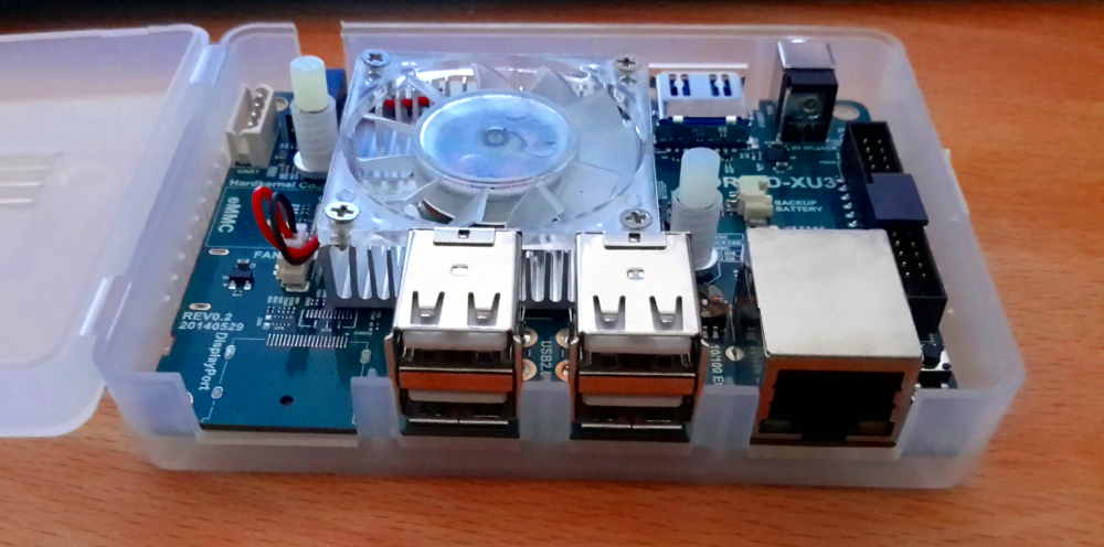
<p>The difference between the original modeline and the new one is the vertical refresh rate: The projector proposed 60.02 Hz via <a href="https://en.wikipedia.org/wiki/Extended_Display_Identification_Data">EDID</a>, and the new modeline is just a tad slower, using 59.94 Hz. I was connecting a ThinkPad T60 to the projector, so the problem might also be the <a href="https://en.wikipedia.org/wiki/RAMDAC">RAMDAC</a> of the laptop, something about <a href="https://en.wikipedia.org/wiki/Video_Graphics_Array#Signal_timings">blank phases</a>, who knows.</p>]]></content><author><name>devsnd</name></author><category term="blog" /><category term="Hardware" /><category term="Linux" /><summary type="html"><![CDATA[If you happen to own an Epson EH-TW5200 projector, you might have experienced problems setting Full-HD (1920×1080) resolution using a VGA connection under linux. When I set the resolution to Full-HD, the whole screen would stay completely black. This is just a quick fix for the other 4 people that might have this problem.]]></summary></entry><entry><title type="html">Homeserver Upgrade: Odroid XU3-Lite Setup on a SD-Card</title><link href="/blog/hardware/linux/server/2015/04/24/Homeserver_Upgrade__Odroid_XU3_Lite_Setup_on_a_SD_Card.html" rel="alternate" type="text/html" title="Homeserver Upgrade: Odroid XU3-Lite Setup on a SD-Card" /><published>2015-04-24T16:32:22+00:00</published><updated>2015-04-24T16:32:22+00:00</updated><id>/blog/hardware/linux/server/2015/04/24/Homeserver_Upgrade__Odroid_XU3_Lite_Setup_on_a_SD_Card</id><content type="html" xml:base="/blog/hardware/linux/server/2015/04/24/Homeserver_Upgrade__Odroid_XU3_Lite_Setup_on_a_SD_Card.html"><![CDATA[<p>I recently bought a new home server, the <a href="http://www.hardkernel.com/main/products/prdt_info.php?g_code=G141351880955">Odroid XU3-Lite</a> to replace my poor man’s home server I called <a href="http://fomori.org/blog/?p=37">the thin-server</a>, to run <a href="http://fomori.org/cherrymusic">CherryMusic</a> and the like.</p>

<p><a href="/assets/images/20150116_120429_small.jpg"><img src="/assets/images/20150116_120429_small.jpg" alt="20150116_120429_small" /></a></p>

<p>That little ARM machine is a beast in the size of a cigarette pack, featuring a total of eight CPU cores, an ethernet port and most importantly an USB 3.0 port to connect an external hard drive. It also comes with a plastic case, with a small fan inside and a PSU that is strong enough to power external hard drives connected to the USB ports. I ordered the smaller “Lite” version, which has a slightly lower CPU clock rate, but costs a lot less than its bigger brother.</p>

<p>In this post I’ll guide you quickly through the installation process of the ubuntu image on a micro SD-Card, how to make use of all the space on the microSD card and how to secure this little fellow a little after the installation of the image.</p>

<h2 id="installing-the-operating-system-image">Installing the Operating System Image</h2>

<p><a href="http://com.odroid.com/sigong/nf_file_board/nfile_board.php?tag=ODROID-XU3">Download the latest Linux image from their site</a> and unpack it using xz:</p>

<div class="language-plaintext highlighter-rouge"><div class="highlight"><pre class="highlight"><code>$ xz --decompress IMAGE_FILE.img.xz
</code></pre></div></div>

<p>The actual image file will of course be called something like ubuntu-14.04.1lts-lubuntu-odroid-xu3-20150212.img.xz and not IMAGE_FILE.img.xz.</p>

<p>Then plug in the SD Card into you linux computer and check out were it was mounted using dmesg.</p>

<div class="language-plaintext highlighter-rouge"><div class="highlight"><pre class="highlight"><code>$ dmesg | tail
... some other output ...
[ 6060.833668] sd 8:0:0:1: [sdX] Attached SCSI removable disk
[ 6077.944503] sd 8:0:0:1: [sdX] 60874752 512-byte logical blocks: (31.1 GB/29.0 GiB)
</code></pre></div></div>

<p>You will see something like sdb or sdc in the output, make sure that you got the letter right; I will use sdX as a placeholder. As you can see I bought a 32 GB SD Card so I would never have to worry what I install on the machine, because there will be more than enough room for it. Also make sure you’re buying a quality SD-Card with fast write rates for better performance.</p>

<p>Now you can copy the image onto the SD-Card.</p>

<p>Warning: All the data on the SD-Card will be lost forever in this process so make sure this SD-Card does not contain any bitcoins or wedding photos you might miss later!</p>

<div class="language-plaintext highlighter-rouge"><div class="highlight"><pre class="highlight"><code>dd if=IMAGE_FILE.img of=/dev/sdX bs=128k
</code></pre></div></div>

<p>Depending on your SD-Card this process may take some minutes and dd will not give you any indication of the progress so be patient.</p>

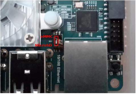
<p>Before you can actually boot from the microSD card, make sure the correct boot mode is set. The ODROID XU3-Lite can either boot from a microSD card or from a eMMC module. There is a tiny switch on the board, to set the the boot mode as explained in the <a href="http://odroid.com/dokuwiki/doku.php?id=en:xu3_bootmode_configuration">ODROID wiki</a>, which I found a bit confusing to be honest. Set the switch as shown in the picture below.</p>

<p><a href="/assets/images/Diagram1.jpeg"><img src="/assets/images/Diagram1.jpeg" alt="Diagram1" /></a></p>

<p>Now you can insert the microSD card and plug it is and it should boot up in about 20 seconds, and automatically connect to your network using DHCP.</p>

<p>Now you can login your new system using SSH from your linux computer (in my case it had the IP 192.168.1.87, but you might need to login to your router to find out what IP the ODROID received):</p>

<div class="language-plaintext highlighter-rouge"><div class="highlight"><pre class="highlight"><code>ssh root@192.168.1.87
</code></pre></div></div>

<p>As always with new SSH connections:</p>

<div class="language-plaintext highlighter-rouge"><div class="highlight"><pre class="highlight"><code> Are you sure you want to continue connecting (yes/no)?
</code></pre></div></div>

<p>Enter “yes” to proceed. The default password is <strong>odroid</strong></p>

<p>First, let’s check how much space I have left on the SD card.</p>

<div class="language-plaintext highlighter-rouge"><div class="highlight"><pre class="highlight"><code>root@odroid:~# df -h
Filesystem      Size  Used Avail Use% Mounted on
/dev/mmcblk0p2  4.9G  4.4G  313M  94% /
none            4.0K     0  4.0K   0% /sys/fs/cgroup
udev            747M  4.0K  747M   1% /dev
tmpfs           998M  4.0K  998M   1% /tmp
tmpfs           200M  2.6M  197M   2% /run
none            5.0M     0  5.0M   0% /run/lock
none            998M   72K  998M   1% /run/shm
none            100M   20K  100M   1% /run/user
/dev/mmcblk0p1  129M  5.1M  124M   4% /media/boot
</code></pre></div></div>

<p>Only some hundred megabytes? Well, thats because the image I flashed onto the SD card also contains the partition layout and the contained file systems, which is as small as possible, so people can use this image also on smaller SD cards. So let’s change that.</p>

<p>First off, partitions are not the same as file systems! So we need to resize the partitions to match the SD card first, and then resize the filesystem to match the partitions.</p>

<h2 id="resize-the-partitions">Resize the partitions</h2>

<p>Since the image was about 6 GB in size, but I bought a 32 GB micro SD card there is a lot of space to be gained. Doing this on a live system is far from a good idea, but since this is the stock system, I don’t care; There’s no data to be lost. Never do this on a system with data you (or somebody else) care about.</p>

<div class="language-plaintext highlighter-rouge"><div class="highlight"><pre class="highlight"><code>root@odroid:~# fdisk -l
 
Disk /dev/mmcblk0: 31.2 GB, 31167873024 bytes
4 heads, 16 sectors/track, 951168 cylinders, total 60874752 sectors
Units = sectors of 1 * 512 = 512 bytes
Sector size (logical/physical): 512 bytes / 512 bytes
I/O size (minimum/optimal): 512 bytes / 512 bytes
Disk identifier: 0x000c4046
 
Device Boot              Start         End      Blocks   Id  System
/dev/mmcblk0p1            3072      266239      131584    6  FAT16
/dev/mmcblk0p2          266240    10915839     5324800   83  Linux
</code></pre></div></div>

<p>So we’ve got 2 partitions here. The first one (/dev/mmcblk0p1) contains the bootloader and the second one contains our ubuntu linux system. By the way: If you ever wondered, mmcblk0p1 stands for Multi Media Card Block Device 0 Part 1. Makes it a bit easier to remember. Let’s write down the total size of the SD card in cylinders somewhere.</p>

<p>So let’s fire up parted to and first check the partition numbers using <em>print.</em></p>

<div class="language-plaintext highlighter-rouge"><div class="highlight"><pre class="highlight"><code>root@odroid:~# parted /dev/mmcblk0
GNU Parted 2.3
Using /dev/mmcblk0
Welcome to GNU Parted! Type 'help' to view a list of commands.           
(parted) print
Model: SD SD32G (sd/mmc)
Disk /dev/mmcblk0: 31.2GB
Sector size (logical/physical): 512B/512B
Partition Table: msdos
Number  Start   End     Size    Type     File system  Flags
 1      1573kB  136MB   135MB   primary  fat16
 2      136MB   5589MB  5453MB  primary  ext4
</code></pre></div></div>

<p>Then we set the unit used by parted to cyl, so when we resize, we can enter the number of total cylinders of the card we wrote down earlier when using fdisk.</p>

<div class="language-plaintext highlighter-rouge"><div class="highlight"><pre class="highlight"><code>(parted) unit cyl
</code></pre></div></div>

<p>Now we can resize the partition 2 (which contains the ext4 filesystem) to use all the available space:</p>

<div class="language-plaintext highlighter-rouge"><div class="highlight"><pre class="highlight"><code>(parted) resizepart 2                                         
Warning: Partition /dev/mmcblk0p2 is being used. Are you sure you want to continue?
Yes/No? yes                                                               
End?  [170559cyl]? 951168
(parted) quit
</code></pre></div></div>

<p>Alright, so now the partition ends at the end of the SD card.</p>

<h2 id="resize-the-file-system">Resize the file system</h2>

<p>Now we can resize the filesystem to the size of the enlarged partition using resize2fs:</p>

<div class="language-plaintext highlighter-rouge"><div class="highlight"><pre class="highlight"><code>resize2fs /dev/mmcblk0p2
resize2fs 1.42.9 (4-Feb-2014)
Filesystem at /dev/mmcblk0p2 is mounted on /; on-line resizing required
old_desc_blocks = 1, new_desc_blocks = 2
The filesystem on /dev/mmcblk0p2 is now 7576064 blocks long.
</code></pre></div></div>

<p>So let’s check the space again:</p>

<div class="language-plaintext highlighter-rouge"><div class="highlight"><pre class="highlight"><code>root@odroid:~# df -h
Filesystem      Size  Used Avail Use% Mounted on
/dev/mmcblk0p2   29G  4.4G   24G  16% /
</code></pre></div></div>

<p>Bam. Now with so much space available, lets fill it with pictures of squirrels. Sometimes I’m overwhelmed by the sheer awesomeness of linux.</p>

<h2 id="create-local-user-and-disable-root-user-login">Create local user and Disable root user login:</h2>

<p>As seen before, your home server can be easily accessed using the default root login, which is not so nice. So lets add another user to login with and also make sure nobody can ssh into the server using the root user.</p>

<p>First add a new user and put that user into the sudo group, so this user can issue all kinds of system commands.</p>

<div class="language-plaintext highlighter-rouge"><div class="highlight"><pre class="highlight"><code>$ adduser USERNAME
$ usermod -a -G sudo USERNAME
</code></pre></div></div>

<p>Now, before we block ssh access for the root user, make sure you can login to the server and execute sudo using the newly created user, or you have locked yourself out of the system!</p>

<p>Now edit /etc/ssh/sshd_config to disable the root login, using any command line text editor (I’m using nano in this case):</p>

<div class="language-plaintext highlighter-rouge"><div class="highlight"><pre class="highlight"><code>$ sudo nano /etc/ssh/sshd_config
</code></pre></div></div>

<p>And now set  PermitRootLogin to No:</p>

<div class="language-plaintext highlighter-rouge"><div class="highlight"><pre class="highlight"><code>PermitRootLogin no
</code></pre></div></div>

<p>Once you have saved the file, you can restart the ssh server to make the changes take effect.</p>

<div class="language-plaintext highlighter-rouge"><div class="highlight"><pre class="highlight"><code>$ sudo service ssh restart
</code></pre></div></div>

<p>That’s it, happy hacking!</p>]]></content><author><name>devsnd</name></author><category term="blog" /><category term="Hardware" /><category term="Linux" /><category term="Server" /><summary type="html"><![CDATA[I recently bought a new home server, the Odroid XU3-Lite to replace my poor man’s home server I called the thin-server, to run CherryMusic and the like.]]></summary></entry><entry><title type="html">How to add USB Gamepad support for your Android phone or tablet</title><link href="/blog/android/hack/hardware/2015/04/11/How_to_add_USB_Gamepad_support_for_your_Android_phone_or_tablet.html" rel="alternate" type="text/html" title="How to add USB Gamepad support for your Android phone or tablet" /><published>2015-04-11T19:41:59+00:00</published><updated>2015-04-11T19:41:59+00:00</updated><id>/blog/android/hack/hardware/2015/04/11/How_to_add_USB_Gamepad_support_for_your_Android_phone_or_tablet</id><content type="html" xml:base="/blog/android/hack/hardware/2015/04/11/How_to_add_USB_Gamepad_support_for_your_Android_phone_or_tablet.html"><![CDATA[<h1 id="img_20150411_201153">IMG_20150411_201153</h1>

<p>I was almost at the point to buy a playstation or xbox controller to use with my tablet, since they seem to be supported out-of-the-box. But actually I still have an old USB controller lying around, which would be more than good enough for playing some games. Interestingly my gamepad did in fact work partly, but only the left analog stick and one or two buttons, and the rest did not. My hacker spirit told me that this must be fixable somehow.</p>

<p>So I started hacking around and added support for my old USB gamepad for my android tablet. In this post, I’ll show you how I did it and how you can to add support for any gamepad to your phone or tablet as well!</p>

<p>First of, your tablet or phone needs to be rooted to make the changes needed to support your gamepad. But just about any device is rootable by now, so a quick search will tell you how to root it, if you haven’t done that already.</p>

<h1 id="prequisites">Prequisites:</h1>

<ul>
  <li>rooted android device</li>
  <li>USB-OTG cable (to connect the gamepad)</li>
  <li>ADB</li>
  <li>A linux computer</li>
  <li>evtest (utility program to read raw gamepad input)</li>
</ul>

<p>Make sure to install evtest and the android debug bridge (adb), which should be available for most linux distributions.</p>

<p>I recommend using ADB wireless to connect to your device, so you can transfer files and type in shell commands while the gamepad is plugged in. I personnally use the open source <a href="https://play.google.com/store/apps/details?id=com.matoski.adbm&amp;hl=en">ADB Manager</a> for that purpose.</p>

<p>And by the way: I am not responsible if you break anything, bla bla. Changing stuff on your android device might as will break it, so proceed with caution. Also, the commands in this how-to are specific to my tablet and gamepad and you have to change them accordingly to your device and hardware.</p>

<h1 id="finding-the-keycodes">Finding the keycodes</h1>

<p>Android maps all gamepad keys to some internal actions. For example some gamepad key with the number 289 is mapped to the action BUTTON_X for some specific keyboard, gamepad or hair-dryer. Here’s <a href="https://source.android.com/devices/input/key-layout-files.html">the documentation of the keymap files</a>, which will tell you a lot about how those are composed. Those keylayouts are inside <em>/system/usr/keylayout/</em> on your android device. So all we need to do to make your gamepad compatible with android, is to create a keylayout that tells android what keys of the gamepad mean which action inside android. That means we have find the keycode and axis ids of all the buttons and map them to the android actions.</p>

<p>First plug in your gamepad into your linux computer. After doing so, run <em>dmesg</em> in a terminal to find out the vendor and product id of your gamepad. This will be important later.</p>

<div class="language-plaintext highlighter-rouge"><div class="highlight"><pre class="highlight"><code>$ dmesg
usb 3-1: new low-speed USB device number 10 using xhci_hcd
usb 3-1: ep 0x81 - rounding interval to 64 microframes, ep desc says 80 microframes
input: Mega World USB Game Controllers as /devices/pci0000:00/0000:00:14.0/usb3/3-1/3-1:1.0/0003:07B5:0315.0008/input/input24
hid-generic 0003:07B5:0315.0008: input,hidraw3: USB HID v1.10 Joystick [Mega World USB Game Controllers] on usb-0000:00:14.0-1/input0
</code></pre></div></div>

<p>In this output, the important part is 07B5:0315, which are the vendor ID <strong>07B5</strong> and the product ID <strong>0315</strong>. Your output might look different depending on your kernel version. If you can’t figure out what’s what, you can also run <em>lsusb</em> to get a more readable output.</p>

<div class="language-plaintext highlighter-rouge"><div class="highlight"><pre class="highlight"><code>$ lsusb
Bus 003 Device 005: ID 8087:07dc Intel Corp.
Bus 003 Device 010: ID 07b5:0315 Mega World International, Ltd
Bus 003 Device 001: ID 1d6b:0002 Linux Foundation 2.0 root hub
</code></pre></div></div>

<p>To find out the key codes you will have to install and use the program <em>evtest</em></p>

<p>To get the raw keycodes, we have to read the signals directly from /dev/input. As there are many devices inside /dev/input, you will have to try out which device is actually your gamepad. Normally it will be the last <em>event</em> device, in my case thats /dev/input/event18.</p>

<div class="language-plaintext highlighter-rouge"><div class="highlight"><pre class="highlight"><code>$ evtest /dev/input/event18
</code></pre></div></div>

<p>Now press some buttons to find out which button has which key code. Pressing a button will yield some output like that:</p>

<div class="language-plaintext highlighter-rouge"><div class="highlight"><pre class="highlight"><code>Event: time 1428772902.008207, type 4 (EV_MSC), code 4 (MSC_SCAN), value 90001
Event: time 1428772902.008207, type 1 (EV_KEY), code 288 (BTN_TRIGGER), value 1
Event: time 1428772902.008207, -------------- EV_SYN ------------
Event: time 1428772902.120190, type 4 (EV_MSC), code 4 (MSC_SCAN), value 90001
Event: time 1428772902.120190, type 1 (EV_KEY), code 288 (BTN_TRIGGER), value 0
Event: time 1428772902.120190, -------------- EV_SYN ------------
</code></pre></div></div>

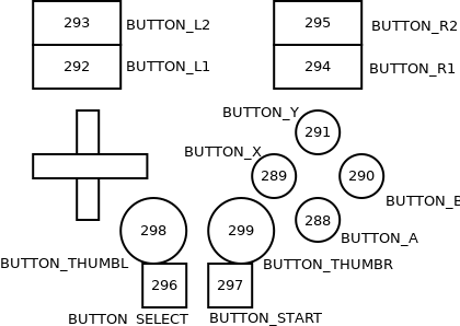
<p>Write down the keycode for that button, in the case above thats 288 for the A-Button, so we can later put it inside the android configuration. For me the following configuration came out. I wrote down all the Buttons that are mapped to something in android.</p>

<p><a href="/assets/images/Diagram1.png"><img src="/assets/images/Diagram1.png" alt="Diagram1" /></a></p>

<p>Also wiggle the analog sticks first horizontally then vertically to find out the axis of each stick. In my case those where axis 0/1 for X/Y left and 2/5 for X/Y right. Using the documentation from the android website and by looking at the other keylayout files on my tablet, I created a configuration file like this:</p>

<div class="language-plaintext highlighter-rouge"><div class="highlight"><pre class="highlight"><code>#
# Mega World USB Game Controllers
#
 
key 288   BUTTON_A
key 290   BUTTON_B
key 289   BUTTON_X
key 291   BUTTON_Y
key 292   BUTTON_L1
key 294   BUTTON_R1
key 293   BUTTON_L2
key 295   BUTTON_R2
key 296   BUTTON_SELECT
key 297   BUTTON_START
key 298   BUTTON_THUMBL
key 299   BUTTON_THUMBR
 
# Left and right stick.
axis 0x00 X
axis 0x01 Y
axis 0x02 RZ
axis 0x05 Z
</code></pre></div></div>

<p>Before you put that configuration file on your device you can optionally use <a href="https://source.android.com/devices/input/validate-keymaps.html">the validate keymaps tool from the android sdk</a> to make sure you didn’t make any mistakes creating the configuration.</p>

<p>The configuration should now be saved to a file that includes the vendor ID and product ID of your gamepad. In my case the vendor ID is 07B5 and the product ID is 0315 so the name my configuration file is <em>Vendor_07b5_Product_0315.kl</em></p>

<p>Android uses the file name to make sure to only load specific configurations for specific USB devices, so make sure those are correct.</p>

<h1 id="adding-the-configuration-to-your-device">Adding the configuration to your device</h1>

<p>After saving the key mapping to <em>Vendor_07b5_Product_0315.kl</em>, we need to upload the file back onto the device. We’ll use adb for that. As described earlier, I recommend using ABD wireless so it’s easier to make changes to the configuration while the gamepad is plugged in.</p>

<p>We put the configuration on the sdcard and move it afterwards to the correct position on the device, because we don’t have root access over adb (so we can’t move the configuration directly into the appropriate system folder)</p>

<div class="language-plaintext highlighter-rouge"><div class="highlight"><pre class="highlight"><code>$ adb connect
$ adb push Vendor_07b5_Product_0315.kl /sdcard/
</code></pre></div></div>

<p>Before you can move the file to the correct location you must remount the <em>/system</em> partition, to make it writable. This may differ from device to device. Check where your <em>/system</em> is mounted using the <em>mount</em> command before. In my case <em>/system</em> is mounted to <em>/dev/block/mmcblk0p20</em>, so I remount that device read-write-able.</p>

<p>Also make sure to allow the adb shell to become root on your tablet once you have entered the <em>su</em> command.</p>

<div class="language-plaintext highlighter-rouge"><div class="highlight"><pre class="highlight"><code>$ adb shell
$ su
$ mount -o remount,rw /dev/block/mmcblk0p20
</code></pre></div></div>

<p>Now we can copy the key layout from the sdcard into the keylayout folder:</p>

<div class="language-plaintext highlighter-rouge"><div class="highlight"><pre class="highlight"><code>$ cp /sdcard/Vendor_07b5_Product_0315.kl /system/usr/keylayout/
</code></pre></div></div>

<p>And really important, you have to change the permissions of the file to 644 or android will not load it after the gamepad was plugged in!</p>

<div class="language-plaintext highlighter-rouge"><div class="highlight"><pre class="highlight"><code>$ chmod 644 /system/usr/keylayout/Vendor_07b5_Product_0315.kl
</code></pre></div></div>

<p>Now you can connect your gamepad to the android device and play some games to check if everything worked out. If something went wrong, you can always upload a new version of you keymap to the sdcard, move it to the system folder, change the permissions and replug your gamepad to make more tests.</p>

<p>Once you have tested that everything works, make sure to remount the <em>/system</em> partition back to read-only.</p>

<div class="language-plaintext highlighter-rouge"><div class="highlight"><pre class="highlight"><code> $ mount -o remount,ro /dev/block/mmcblk0p20
</code></pre></div></div>

<p>And now I can finally play GTA: San Andreas on my tablet using my really old cheapo USB Gamepad, which is incredibly better than the touch controls. Great.</p>]]></content><author><name>devsnd</name></author><category term="blog" /><category term="Android" /><category term="Hack" /><category term="Hardware" /><summary type="html"><![CDATA[IMG_20150411_201153]]></summary></entry><entry><title type="html">DIY: Black Rolls/Trigger Point-like foam rollers for myofascial release</title><link href="/blog/handycrafts/mod/2015/03/01/DIY__Black_Rolls_Trigger_Point_like_foam_rollers_for_myofascial_release.html" rel="alternate" type="text/html" title="DIY: Black Rolls/Trigger Point-like foam rollers for myofascial release" /><published>2015-03-01T14:41:35+00:00</published><updated>2015-03-01T14:41:35+00:00</updated><id>/blog/handycrafts/mod/2015/03/01/DIY__Black_Rolls_Trigger_Point_like_foam_rollers_for_myofascial_release</id><content type="html" xml:base="/blog/handycrafts/mod/2015/03/01/DIY__Black_Rolls_Trigger_Point_like_foam_rollers_for_myofascial_release.html"><![CDATA[<p><a href="/assets/images/Cover-1-Black-Rolls.png"><img src="/assets/images/Cover-1-Black-Rolls-300x199.png" alt="Black Rolls" /><img src="/assets/images/Cover-2-Finished-DIY-version-300x209.png" alt="Finished DIY version" /></a></p>

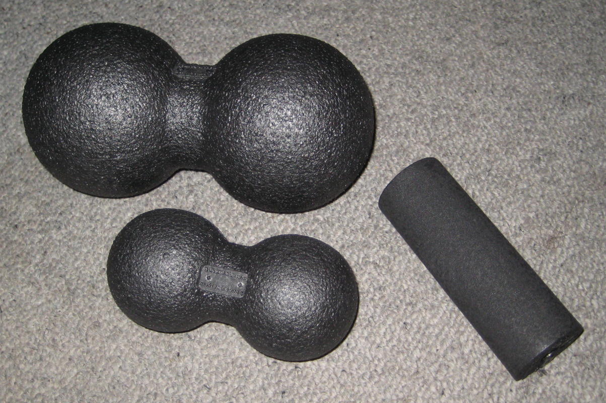
<p>I am a big fan of using foam rollers for <a href="https://en.wikipedia.org/wiki/Myofascial_Release" title="en.wikipedia.org - myofascial release">myofascial release</a>, especially after workout.</p>

<p>There are a lot of foam roller products for <a href="https://en.wikipedia.org/wiki/Trigger_point" title="en.wikipedia.org - trigger point">myofascial trigger point</a> treatment out there, but I am too cheap to buy a piece of recycled plastic pressed into a cylindrical form for 20 EUR or higher. This is one of the easiest <a href="https://en.wikipedia.org/wiki/Do_it_yourself" title="en.wikipedia.org - Do it yourself">DIY</a> projects possible, so make your own!</p>

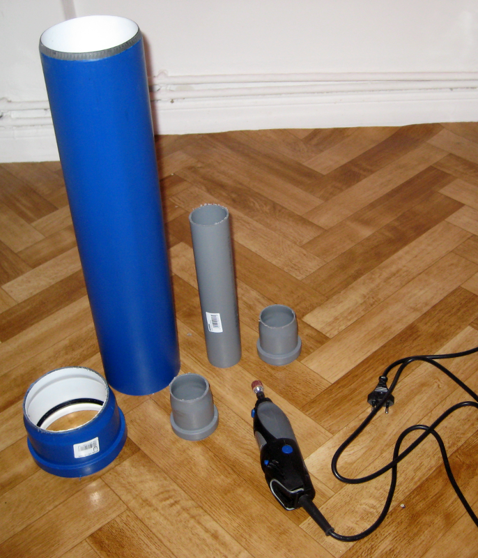
<p>The standard foam rollers of different sizes can be replaced with almost anything that has a similar form and supports your weight. I used <a href="https://en.wikipedia.org/wiki/Polyvinyl_chloride#Pipes" title="en.wikipedia.org - Polyvinyl chloride - Pipes">PVC tubes</a> from a hardware store nearby. Just chose your preferred diameter, cut of the flange (using a <a href="https://en.wikipedia.org/wiki/Dremel" title="en.wikipedia.org - Dremel">Dremel</a> or a standard saw) and you are done.</p>

<p><a href="/assets/images/Flange-removed.png"><img src="/assets/images/Flange-removed-257x300.png" alt="Flange removed" /></a>Now for the back area, foam rollers exist in the form of two spheres connected in one point.</p>

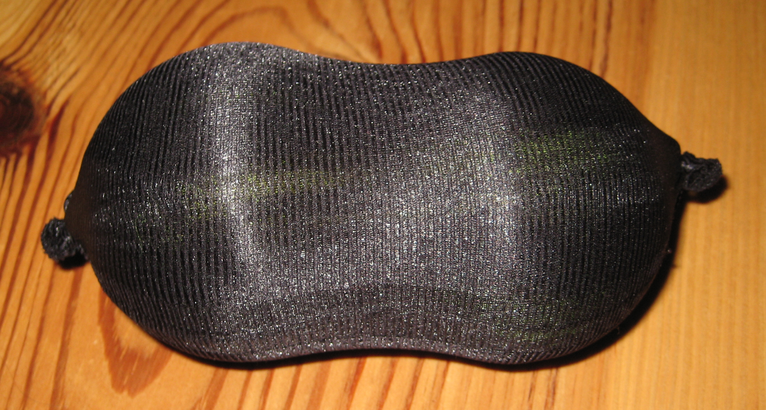
<p>The small version can easily be replicated by putting two tennis balls into <a href="https://en.wikipedia.org/wiki/Nylon" title="en.wikipedia.org - nylon">nylon</a> tights and tying a knot at the end. This might sound/look a little strange, but seriously it works well (although the tennis balls are almost a little too soft).</p>

<p><a href="/assets/images/Tennis-balls-in-nylon-tights.png"><img src="/assets/images/Tennis-balls-in-nylon-tights-300x212.png" alt="Tennis balls in nylon tights" /></a>For higher durability, add a few more nylon layers.</p>

<p><a href="/assets/images/Tennis-balls-in-nylon-tights-more-layers.png"><img src="/assets/images/Tennis-balls-in-nylon-tights-more-layers-300x160.png" alt="Tennis balls in nylon tights - more layers" /></a>You can probably think of a bigger and harder version and probably find a lot of (even better) alternatives for foam rollers.</p>

<p>Happy foam rolling!</p>]]></content><author><name>6arms1leg</name></author><category term="blog" /><category term="Handycrafts" /><category term="Mod" /><summary type="html"><![CDATA[]]></summary></entry><entry><title type="html">Samsung Galaxy S3 repair – Glass screen/digitizer replacement and why it is not recommended</title><link href="/blog/android/hack/handycrafts/hardware/2015/03/01/Samsung_Galaxy_S3_repair___Glass_screen_digitizer_replacement_and_why_it_is_not_recommended.html" rel="alternate" type="text/html" title="Samsung Galaxy S3 repair – Glass screen/digitizer replacement and why it is not recommended" /><published>2015-03-01T13:27:24+00:00</published><updated>2015-03-01T13:27:24+00:00</updated><id>/blog/android/hack/handycrafts/hardware/2015/03/01/Samsung_Galaxy_S3_repair___Glass_screen_digitizer_replacement_and_why_it_is_not_recommended</id><content type="html" xml:base="/blog/android/hack/handycrafts/hardware/2015/03/01/Samsung_Galaxy_S3_repair___Glass_screen_digitizer_replacement_and_why_it_is_not_recommended.html"><![CDATA[<p><a href="/assets/images/Cover-Glass-screen-replaced.png"><img src="/assets/images/Cover-Glass-screen-replaced-300x208.png" alt="Glass screen replaced" /></a>A friend asked me to repair her friends <a href="https://en.wikipedia.org/wiki/Samsung_Galaxy_S_III" title="en.wikipedia.org - Samsung Galaxy S III">Samsung Galaxy S3</a> mobile phone, that had a broken glass screen/digitizer, so I had a closer look at it. The process of replacing the glass screen/digitizer on a Samsung Galaxy S3 is straight forward and not many tools are needed. However, what you really need is patience… a lot of it.</p>

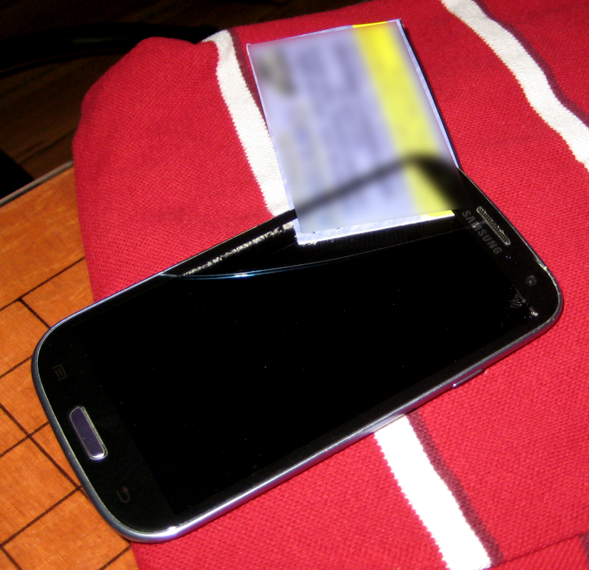
<p>This post shows how it is done and why I still would not recommend it anyway.</p>

<p>Please note the difference between a broken glass screen/digitizer and a broken display! The display is the actual electronic part, while the glass screen/digitizer is… well, just a glass screen glued on top of the real display. A broken display can also be repaired (=replaced), but since the display essentially “is” the mobile phone (with most parts soldered onto it as <a href="https://en.wikipedia.org/wiki/Surface-mount_technology" title="en.wikipedia.org - surface-mount device">SMD</a>s) it makes no economic sense — buying a new phone would be the right way to go here.</p>

<p>Also be advised, that these instructions can — if not applied correctly — lead to a (completely) broken and unusable phone. You do this at your own risk!</p>

<h1 id="replacing-the-glass-screendigitizer">Replacing the glass screen/digitizer</h1>

<p>Technically, replacing the glass screen/digitizer is very easy: all you need is the replacement part (make sure it ships with the necessary adhesive included!), a hairdryer, tweezers, alcohol (~70% ethanol) and a deck of cards (you probably get the wrong impression now, so please read on 😉 ).</p>

<p>Simply put, the display is mounted into the casing with some industrial grade adhesive. The same adhesive is used to merge the glass screen/digitizer with the display (with a layer in between). This adhesive effect can be reduced by applying moderate heat.</p>

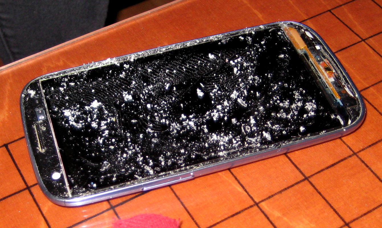
<p>Start by removing the back cover and the battery. Then gently apply (moderate) heat with the hairdryer at the top front, but be careful not to heat it up too much. Then start fiddling a card from your card deck (I used a laminated business card) between the glass screen/digitzer and the case. In this initial step, it might be better to use a razor blade (be careful!) just to open the first gap to insert a card. Only use non-scratching tools (like a card) from here on to protect the display. Also make sure to start at the top front on the left side (see figure below). This is the least sensitive region of the screen.</p>

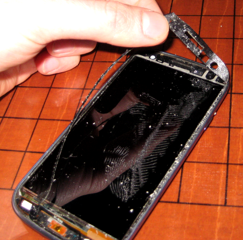
<p><a href="/assets/images/Seperating-glass-screen-from-display.png"><img src="/assets/images/Seperating-glass-screen-from-display-300x290.png" alt="Seperating glass screen from display" /></a>Now work your way downwards to the bottom of the screen with the same procedure: heat up a small area of the screen and then gently push down the card a little further. Be very very patient and careful during these steps! It takes quite a long time to completely remove the glass screen/digitizer (it took me about an hour) and only a little too much pressure or not enough heat will break the display underneath, in which case the phone will be trash. Often, you can barely hear/see the display crack. If you are not sure if your display is still functional just put the battery back in and turn it on — if it is broken stop right there and save the trouble of dismantling the phone any further.</p>

<p>Once you reach the area with the three buttons at the bottom, work your way around them. you will notice that the touch buttons are also glued to the glass screen/digitzer and connected via a flex cable. This is the most tricky part, as it is too easy to rip them off.</p>

<p><a href="/assets/images/Glass-screen-removed.png"><img src="/assets/images/Glass-screen-removed-300x178.png" alt="Glass screen removed" /></a></p>

<p>Now, remove the black rubber seal from the fringe.</p>

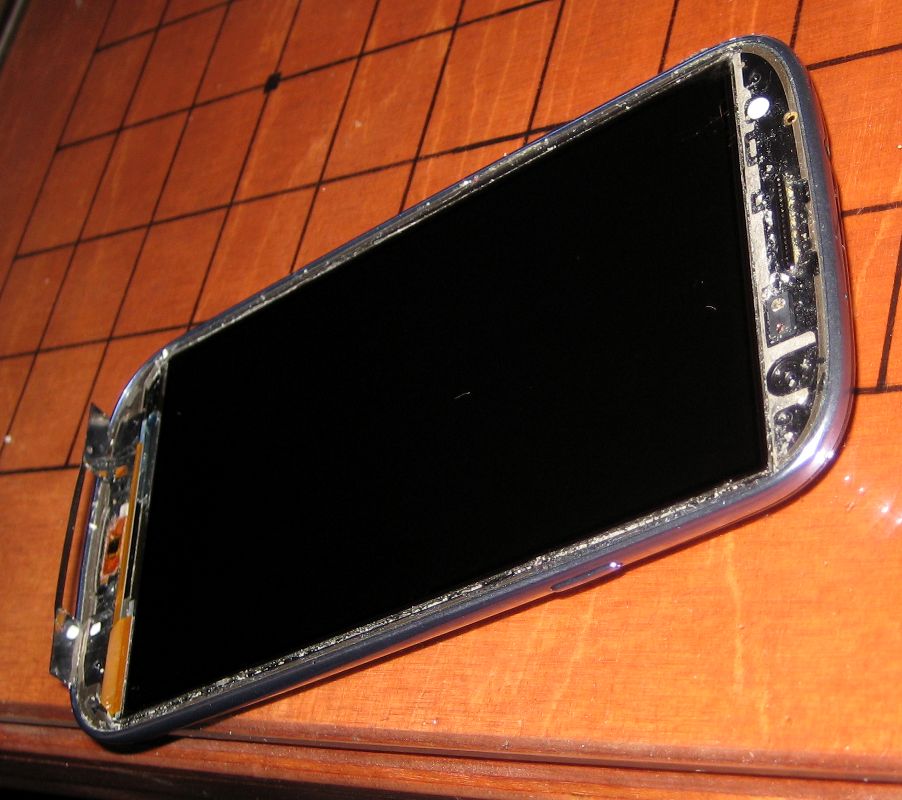
<p><a href="/assets/images/Removing-rubber-seal.png"><img src="/assets/images/Removing-rubber-seal-300x296.png" alt="Removing rubber seal" /></a>Then remove all the adhesive that is left on the display and clean the display with ethanol and a (antistatic) cloth.</p>

<p><a href="/assets/images/Cleaned.png"><img src="/assets/images/Cleaned-300x266.png" alt="Cleaned" /></a>Once the display and the surrounding fringe are completely free of adhesive, place small stripes of adhesive tape (the one that was shipped with the replacement part) around the display. Fill as much surface around the display with adhesive as possible. Tweezers can be of great help here.</p>

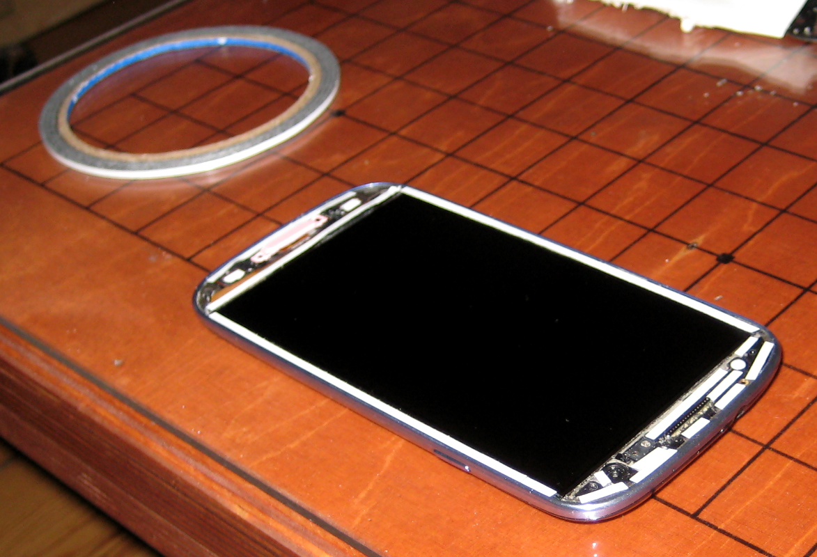
<p><a href="/assets/images/Adhesive-tape-applied.png"><img src="/assets/images/Adhesive-tape-applied-300x204.png" alt="Adhesive tape applied" /></a>Finally, remove all protective foil from the adhesive tape stripes and the one at the bottom of the replacement glass screen/digitizer. Make sure the display is completely free of any dirt particles and the three buttons are in place and carefully place the new glass screen/digitizer onto the display, beginning at the top using the notch for the speaker as reference point. Once the glass screen/digitizer and display are aligned perfectly, apply moderate pressure to merge both parts.</p>

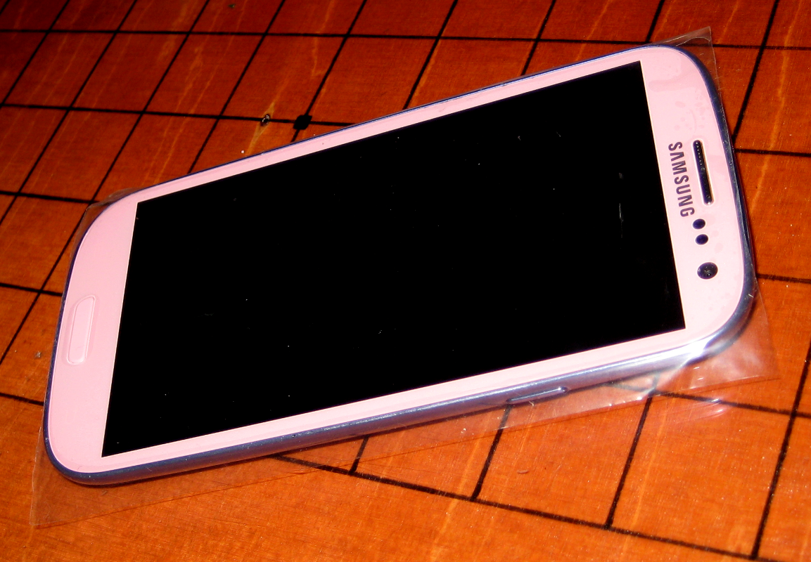
<p><a href="/assets/images/Cover-Glass-screen-replaced.png"><img src="/assets/images/Cover-Glass-screen-replaced-300x208.png" alt="Glass screen replaced" /></a>Please do not ask why the replacement is pink!^^</p>

<h1 id="still-working-and-why-it-is-not-recommended">Still working… and why it is not recommended</h1>

<p>This repair method is quite tricky and can easily destroy your phone. I also broke the display of the first mobile phone I tried to repair.</p>

<p>Also, on a new device, the adhesive layer between the glass screen/digitizer and the display covers the whole display area, not only the fringe. Most standard/cheap replacements (like the method shown here) are applied with adhesive tape, rather than the liquid adhesive that also covers the display area. With the lack of that adhesive layer between glass screen/digitizer and display, a thin, empty gap between both remains. Pressing down on the screen with a little more pressure locally produces strange artifacts, much like pressing on the screen of a notebook. This by the way is an easy method to find out if the glass screen/digitizer was replaced in a cheap manner on a second hand device.</p>

<p>While this mobile phone model is not waterproof to begin with, this repair method reduces it’s water resistance even further. The cheap adhesive tape seals the phone even worse than the original adhesive.</p>

<p>So if the glass screen/digitizer shows only small cracks with the touch functionality still working and the display still readable, better use the phone as it is. On the other hand, if the glass screen/digitizer is severely scattered, this might be a cheap solution to make the phone working again.</p>

<p>You have been warned!</p>]]></content><author><name>6arms1leg</name></author><category term="blog" /><category term="Android" /><category term="Hack" /><category term="Handycrafts" /><category term="Hardware" /><summary type="html"><![CDATA[A friend asked me to repair her friends Samsung Galaxy S3 mobile phone, that had a broken glass screen/digitizer, so I had a closer look at it. The process of replacing the glass screen/digitizer on a Samsung Galaxy S3 is straight forward and not many tools are needed. However, what you really need is patience… a lot of it.]]></summary></entry><entry><title type="html">DIY: “barefoot”/natural running shoes</title><link href="/blog/handycrafts/mod/2015/02/28/DIY___barefoot__natural_running_shoes.html" rel="alternate" type="text/html" title="DIY: “barefoot”/natural running shoes" /><published>2015-02-28T21:06:29+00:00</published><updated>2015-02-28T21:06:29+00:00</updated><id>/blog/handycrafts/mod/2015/02/28/DIY___barefoot__natural_running_shoes</id><content type="html" xml:base="/blog/handycrafts/mod/2015/02/28/DIY___barefoot__natural_running_shoes.html"><![CDATA[<p><a href="/assets/images/Cover-Finished-sole.png"><img src="/assets/images/Cover-Finished-sole-300x242.png" alt="Finished sole" /></a></p>

<p>At the end of last year I went to a sports and health fair, where I wanted to have a closer look at the available natural running shoes, especially the ones from <a href="http://vibram.com/fivefingers" title="Vibram.com - FiveFingers">Vibram (FiveFingers)</a> and <a href="http://www.leguano.eu/" title="leguano.eu">Leguano</a>. Both type of shoes were comfortable and seemed to be of good quality. However, with an above the 70 EUR price range, they are quite expensive for a shoe that aims to be like no shoe at all. In fact, they are more like a pair of high quality socks with a special thin rubber layer glued to the sole (whereas the Vibram FiveFingers also seem to have some supportive structure integrated, which is kind of a contradiction to the barefoot philosophy). Making a custom fitted version should not be that hard, so I decided to make my own.</p>

<p>Since most ideas already exist somewhere in the internet, I found several <a href="https://www.youtube.com/watch?v=WRCXy_UHPVc" title="youtube.com - How To Make Minimalist Running/Climbing Shoes At Home">youtube video</a>s, where they were making their own pair of Vibram FiveFingers fakes. Actually, I find the separate toe sections quite annoying — not only because you can only wear them barefoot or with special socks, but also because it takes practice and more time to put them on. Not separating the toe sections makes the building process very simple.</p>

<p>All that is needed is:</p>

<ul>
  <li>a pair of high quality socks (designed for sports),</li>
  <li>one of the available liquid rubber products (<a href="http://www.plastidip.com" title="plastidip.com">Plasti Dip</a>, <a href="http://www.rustoleum.com/en/product-catalog/consumer-brands/flexidip/flexidip" title="FlexiDip">FlexiDip</a>, <a href="http://sugru.com/about/" title="Sugru">Sugru</a>, latex milk, etc.)</li>
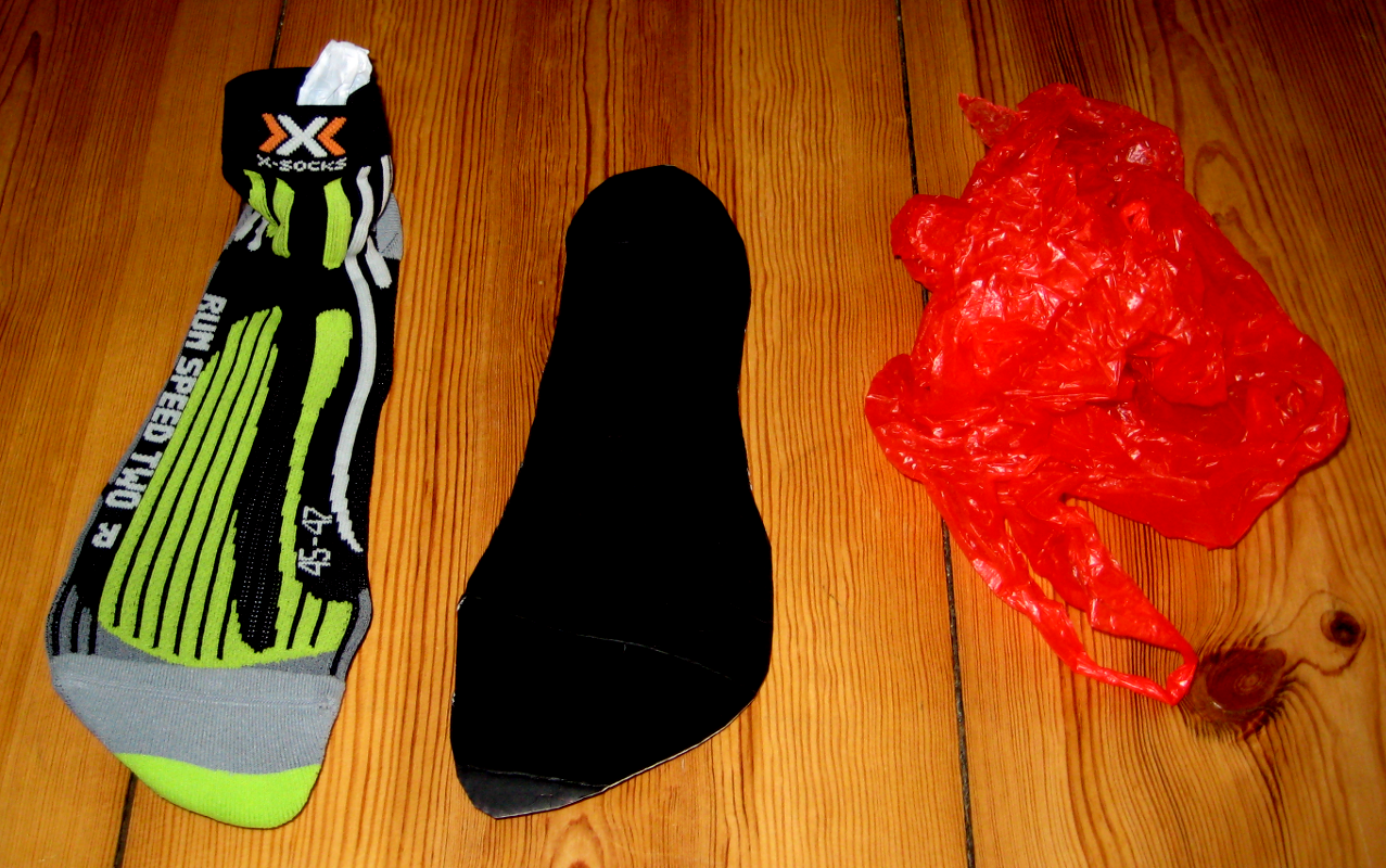
  <li>a piece of cardboard big enough to place your feet on it, a pen and two plastic bags</li>
</ul>

<p><a href="/assets/images/BOM.png"><img src="/assets/images/BOM-300x283.png" alt="Bill of material" /></a>For my version I used a Plasti Dip spray, but I would expect latex milk to give an even better result.</p>

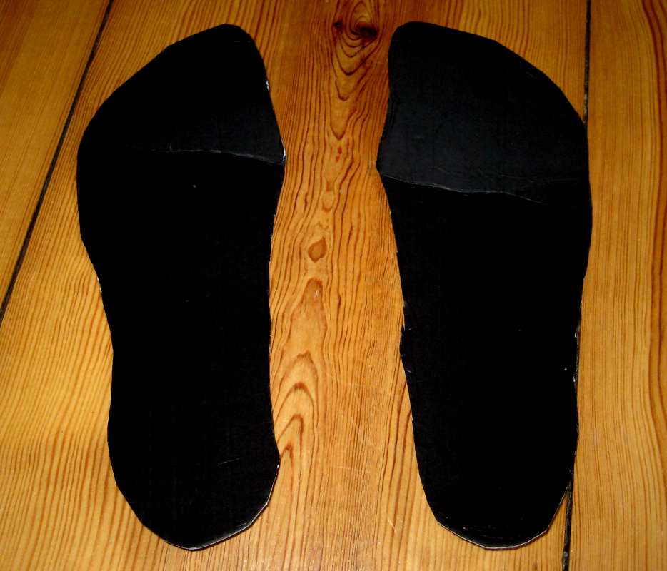
<p>First place your feet on the cardboard and draw their outline with a pen on the board. The outline should be the shape of your feet seen from above. Hold the pen vertically while drawing around your foot, making the contour slightly bigger than your actual foot. Do not pay too much attention to the details, just roughly match your foot’s sole. The surface of these two cardboard outlines will be transferred to the sole of your socks in the next step.</p>

<p><a href="/assets/images/Cardboard-outlines.png"><img src="/assets/images/Cardboard-outlines-300x256.png" alt="Cardboard outlines" /></a>Do not try to simply put on the socks and spray/paint the sole. The liquid rubber paint will soak into the textile and onto your skin. With latex milk this is no problem, but Plasti Dip should not come in contact with skin until dry. Also, several layers need to be painted. During the painting process, each layer needs to dry, which would leave you waiting with the shoes on.</p>

<p>Now, put each cardboard outline into a plastic bag (this reduces the friction, makes the cardboard easier to place in the socks and prevents any cuts in the textile) and then carefully place them into the socks. Make sure the socks fit the cardboard perfectly, as the bottom of the socks will be painted and eventually become the sole of your new shoes.</p>

<p><a href="/assets/images/Cardboard-and-plastic-bag-in-sock.png"><img src="/assets/images/Cardboard-and-plastic-bag-in-sock-300x187.png" alt="Cardboard and plastic bag in sock" /></a>Now you start to build up the sole of your shoes by applying the liquid rubber to the sole of the socks layer by layer. Give each layer enough time to dry (see the liquid rubber product’s user instructions). Obviously, the more layers you add, the thicker the soles of your shoes become — it is up to you.</p>

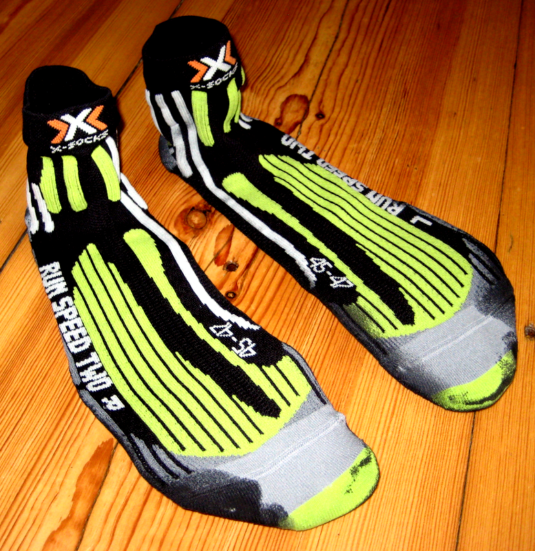
<p>When the sole is dry and has the desired thickness, you are done. Remove the cardboard and plastic bags and try on your new shoes.</p>

<p><a href="/assets/images/Finished-top.png"><img src="/assets/images/Finished-top-291x300.png" alt="Finished shoe top" /></a><a href="/assets/images/Cover-Finished-sole.png"><img src="/assets/images/Cover-Finished-sole-300x242.png" alt="Finished sole" /></a>Do not expect anything similar to “normal” shoes. These are just socks with a rubber sole. They are great (and quite durable) in all situations, where you would like to have a barefoot feeling while still wearing shoes. Unlike Vibram FiveFingers and Leguanos, they do not protect your foot from sharp objects on the ground, so be careful where you use them. And just as with all “barefoot”/natural running shoes, I would not recommend walking with them on hard surfaces (e.g. asphalt).</p>]]></content><author><name>6arms1leg</name></author><category term="blog" /><category term="Handycrafts" /><category term="Mod" /><summary type="html"><![CDATA[]]></summary></entry><entry><title type="html">QCAD – Symbols, special characters and font styles in dimension labels</title><link href="/blog/hack/linux/software/2014/08/20/QCAD___Symbols__special_characters_and_font_styles_in_dimension_labels.html" rel="alternate" type="text/html" title="QCAD – Symbols, special characters and font styles in dimension labels" /><published>2014-08-20T16:19:20+00:00</published><updated>2014-08-20T16:19:20+00:00</updated><id>/blog/hack/linux/software/2014/08/20/QCAD___Symbols__special_characters_and_font_styles_in_dimension_labels</id><content type="html" xml:base="/blog/hack/linux/software/2014/08/20/QCAD___Symbols__special_characters_and_font_styles_in_dimension_labels.html"><![CDATA[<p><a href="/assets/images/Cover-QCAD-with-Alpha-and-l_ABz-dimensions.png"><img src="/assets/images/Cover-QCAD-with-Alpha-and-l_ABz-dimensions.png" alt="Cover - QCAD with Alpha and l_ABz dimensions" /></a></p>

<p><a href="http://www.qcad.org/en/" title="qcad.org">QCAD</a> is a great free and open source <a href="https://en.wikipedia.org/wiki/Computer-aided_design" title="en.wikipedia.org - Computer-aided_design">CAD</a> software. Although limited to 2D design, it is my favorite tool for drafting, construction and simple sketches. It is <a href="http://www.qcad.org/en/qcad-documentation" title="qcad.org/en - qcad-documentation">well documented</a> overall, but one issue I could not find a solution for, was how to label dimensions with symbols, special characters or certain font styles (bold, italic, super-/subscript).</p>

<p>This blog post provides a simple trick to get it done.</p>

<p>If you try to label the dimension of an angle with a symbol (like “α” or “β”) for example, QCAD will only show a question mark (“?”) as a place holder:</p>

<p><a href="/assets/images/QCAD-with-dimension.png"><img src="/assets/images/QCAD-with-dimension.png" alt="QCAD with ? dimension" /></a></p>

<p>To get QCAD to display symbols, special characters or certain font styles (bold, italic, super-/subscript) in dimension labels, the desired label in the label text field must be provided in a certain text format:</p>

<div class="language-plaintext highlighter-rouge"><div class="highlight"><pre class="highlight"><code>\fFONT|b0|i0|c0|p0;LABELTEXT
</code></pre></div></div>

<table>
  <tbody>
    <tr>
      <td>FONT – desired font; LABELTEXT – text (or symbols, etc.) to label the dimension with; “</td>
      <td>b0</td>
      <td>i0</td>
      <td>c0</td>
      <td>p0;” – each entry takes “0” or “1” to switch font styles (bold, italic, etc.)</td>
    </tr>
  </tbody>
</table>

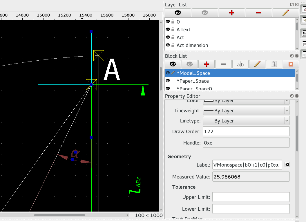
<p>For example (α in italic monospace for an angle dimension label):</p>

<div class="language-plaintext highlighter-rouge"><div class="highlight"><pre class="highlight"><code>\fMonospace|b0|i1|c0|p0;α
</code></pre></div></div>

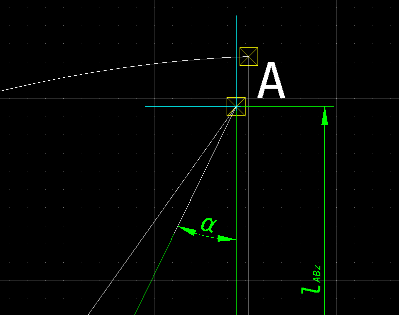
<p><a href="/assets/images/QCAD-with-Alpha-dimension.png"><img src="/assets/images/QCAD-with-Alpha-dimension.png" alt="QCAD with Alpha dimension" /></a></p>

<p>Super- and subscript font styles are also possible by using:</p>

<div class="language-plaintext highlighter-rouge"><div class="highlight"><pre class="highlight"><code>\SSUPERSCRIPT^;
</code></pre></div></div>

<p>or</p>

<div class="language-plaintext highlighter-rouge"><div class="highlight"><pre class="highlight"><code>\S^SUBSCRIPT;
</code></pre></div></div>

<p>SUPERSCRIPT – text in superscript; SUBSCRIPT – text in subscript</p>

<p>E.g., for the italic “<em>lABz</em>” length dimension label in the above illustration that would be:</p>

<div class="language-plaintext highlighter-rouge"><div class="highlight"><pre class="highlight"><code>\fMonospace|b0|i1|c0|p0;l\S^ABz;
</code></pre></div></div>

<p>It may not be the most user friendly way to format text (the normal text tool in QCAD does a far better job), but it works.</p>]]></content><author><name>6arms1leg</name></author><category term="blog" /><category term="Hack" /><category term="Linux" /><category term="Software" /><summary type="html"><![CDATA[]]></summary></entry></feed>